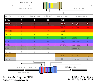
The electronic color code discussed here is used to indicate the values or ratings of electronic components, very commonly for resistors, but also for capacitors, inductors, and others. A separate code, the 25-pair color code, is used to identify wires in some telecommunications cables. Colorbands were commonly used (especially on resistors) because they were easily printed on tiny components, decreasing construction costs. However, there were drawbacks, especially for color blind people. Overheating of a component, or dirt accumulation, may make it impossible to distinguish brown from red from orange. Advances in printing technology have made printed numbers practical for small components, which are often foun The standard color code per EN 60062:2005 is as follows: Color Significant figures Multiplier Tolerance Temp. Coefficient (ppm/K)
1.Black 0 ×100 – 250 U 2.Brown 1 ×101 ±1% F 100 S 3.Red 2 ×10² ±2% G 50 R 4.Orange 3 ×10³ – 15 P 5.Yellow 4 ×10⁴ – 25 Q 6.Green 5 ×10⁵ ±0.5% D 20 Z Blue 6 ×10⁶ ±0.25% C 10 Z 7.Violet 7 ×10⁷ ±0.1% B 5 M 8.Gray 8 ×10⁸ ±0.05% A 1 K 9.White 9 ×10⁹ – – 10.Gold – ×10-1 ±5% J – 11.Silver – ×10-2 ±10% K – 12.None – – ±20% M – d in modern electronics.
Thursday, April 29, 2010
Color codes on electron
Posted by Faria at 1:41 AM
Subscribe to:
Post Comments (Atom)
0 comments:
Post a Comment